Spatial Audio Rendering
Systems and methods for making spatial audio with panel loudspeakers - specifically primary audio sources that can be dynamically moved to different parts of the surface - are described on this page. Employing these methods on a display gives the potential for an immersive multimedia system for object-based audio that can spatially align audio sources with their corresponding visual images. As with the work on panel loudspeakers, Mark Bocko and Dave Anderson were also major contributors to this work. Much of this work is included in a review paper on flat-panel loudspeakers that the three of us (plus Steve Roessner) were invited to write for the Journal of the Audio Engineering Society.
Natural Vibration Localization on Panels
In two and three-dimensional distributed systems such as panels and rooms, the frequency separation between modal resonances decreases with increasing resonant frequency. This means that at low frequencies, the mechanical frequency response of a panel clearly shows the contributions of isolated individual modes, while at high frequencies, the response of the panel is characterized by the superposition of many overlapping modes, i.e., when the mode separation is much less than the frequency bandwidth of the individual modes. When many modes are simultaneously excited, the vibrations naturally localize around the driving element. The displacement amplitudes of individual modes are shown vs. frequency in the animation below. Notice how the resonant peaks show significant overlap with increasing frequency. The other animation shows the corresponding panel response. At high-frequencies, individual modes can no longer be distinguished. This natural localization is emphasized in highly damped panels where the actuators are placed near the edges.


Modal Superposition
At low frequencies, where vibrations do not localize naturally, an actuator array can be used to localize vibrations by selectively driving modes with the amplitudes needed to approximate the band-limited spatial Fourier series of a target vibration region. In the example below, a linear combination of the eight lowest-frequency bending modes can be used to produce a localized sound source in the upper right corner.

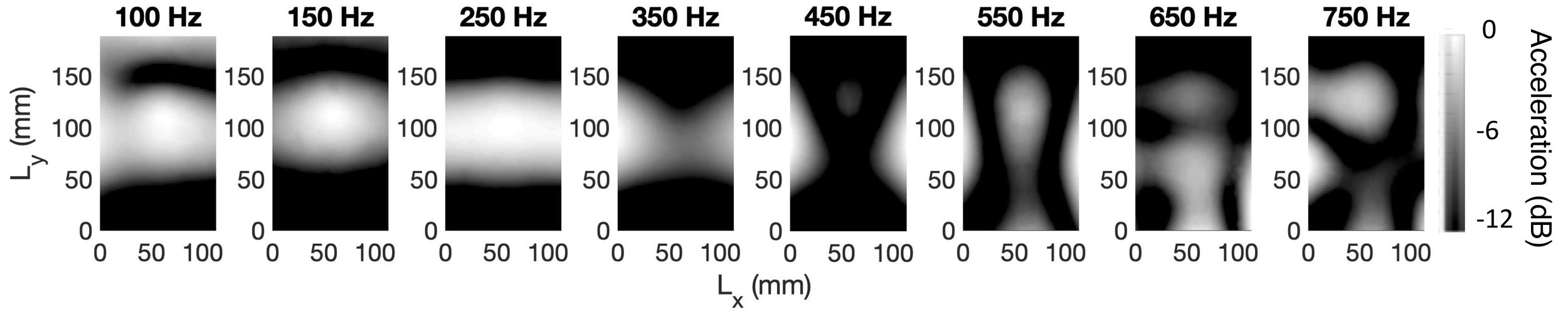
Since the amplitude of each mode is frequency dependent, a filter can be designed based on models for the mechanical response of the panel, the panel’s physical properties, and the actuator locations to maintain the proper relative modal amplitudes throughout the bandwidth of the array. At frequencies above the array bandwidth, the vibration response will alias to another mode. This can be seen in the measurements below, where the localized shape is maintained until the (1,6) mode is aliased at 3,406 Hz. Note that the below image is flipped horizontally relative to the top image because the vibrometer scan is taken from the front.


Object-Based Audio
A natural application of this vibration localization is aligning sound sources with their corresponding images on a display. This is well suited for object-based encoding of audio, where each object is given a spatial position rather than a channel number, and the object render decides how best to reproduce that audio signal at the encoded spatial location given the constraints of the rendering system. In the case of a panel, the object renderer must account for the changing vibration behavior of the panel in different frequency regions. We propose a three-way crossover network to separate the signal into low, mid, and high-frequency bands. The high-frequency and midrange bands are send to the object renderer, where the midrange signal is reproduced through using the modal superposition algorithm described above at the object’s location, and the high-frequency band is reproduced through the actuator in closest proximity to the source position specified in the metadata since vibrations naturally localize at high-frequencies. Low-frequency audio below 150 Hz is sent directly through the driver array to be reproduced through the fundamental mode for enhanced bass, as these low-frequency signals do not provide much spatial information perceptually. An example of the decoder for MPEG-H 3D Audio is shown below along with measurements of the system working with a large panel.


Non-Uniform Boundary Conditions
The above model for modal superposition is only realizable if the shapes and resonant frequencies of the modes are known. In most cases, the boundary conditions of the panel are not easily modeled, so the vibration response must be determined empirically. We employ a scanning laser vibrometer to determine the response of the panel to each driver individually. The magnitudes and phases of each of the responses are then optimized at each frequency so that the combined response of all the actuators (with the optimized filters applied) approximates a target vibration region. An example of this is shown for the simply supported panel shown in the modal superposition section, but also for an acrylic panel supported only by for standoffs (one in each corner). The top figure in each scan is the response of a single actuator D3. The bottom figure in each scan in is the empirically determined localized response using the actuator array.